Task 1
PID Controller Implementation
Why PID for Line Following?
A line-following robot’s main task is to track a black line over a white surface or vise versa. The challenge lies in keeping the robot centered on the line while moving at a reasonable speed.
- Bang-bang control (pure if–else switching) can make the robot jittery because it overcorrects.
- PID control continuously adjusts the motor speeds, leading to smooth motion, less oscillation, and faster convergence to the line.
PID works by measuring the error (distance from center of the line), and applying corrective motor commands proportional to that error and its history.
Understanding Sensor Arrangement
The robot has 5 reflective sensors in a row:
[ sen0 | sen1 | sen2 | sen3 | sen4 ]
- White surface: High readings (close to 1).
- Black line: Low readings (close to 0).
The middle sensor (sen2) corresponds to the “ideal” line position.
To keep the robot in ideal position, one approach can be to set a threshold:
if sensor value > threshold → detect white.
else → detect black.
But this binary method loses information:
- It can’t tell if the line is slightly left or far left.
- It leads to jerky movements because the control system only knows “on” or “off”.
Thus, instead of binary logic, we use a continuous measure of where the line is under the sensors. This is where the weighted average method comes in.
Weighted Average Concept
The weighted average comes from position sensing and centroid estimation in robotics and computer vision.
- Imagine the black line as a “mass distribution” seen by the sensors.
- Each sensor has a “weight” that represents its physical position relative to the center.
- By multiplying the sensor value with its weight and dividing by the total sensor response, we get an average position of the line.
Mathematically:
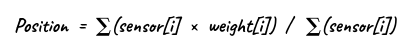
where weights = [-2, -1, 0, +1, +2]
Now if only sen2 (center) detects the line, numerator = 0 → position = 0.
If sen0 (far left) detects the line, numerator is strongly negative → position < 0.
If sen4 (far right) detects the line, numerator is strongly positive → position > 0.
Thus, the position value directly proporional on how far left/right the robot is from the line center.
Error Definition
We define a setpoint (ideal position) = 0.
error = setpoint − position
If error = 0 → robot is perfectly centered.
If error > 0 → line is left of robot (must turn left).
If error < 0 → line is right of robot (must turn right).
Applying PID Output to Motor Control
We have already seen the proper mathematical formula for PID:
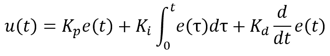
For discrete robotics systems:
Proportional (P): Responds to present error.

Integral (I): Accumulates past error (reduces bias).

Derivative (D): Predicts future error by observing rate of change.
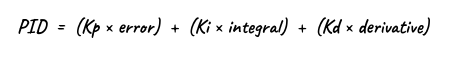
Use this PID value to differentially adjust speeds of both the motors.
vl = baseSpeed − PID
vr = baseSpeed + PID
Clamp motor outputs between 0–100 to avoid saturation.
After completing the above steps, the next crucial task is tuning the PID controller to ensure that the robot follows the line with both smoothness and high accuracy.